| LDPW |
| Mole Mart |
| SLRR switch |
 参考 |
 |
 |
 |
 |
 |
 Railway Switches and Signals |
Official SLRR Switch Stand Documentation 
These Switch Stands are rather complicated to setup. Knowledge of object UUID and script editing is needed as well as comprehensive building experience. Also is it important to move slowly and stay organized during the setup. I hope these setup instructions and diagrams simplify your Switch installation.
More information on track standards can be found in the SL wiki.
Please note no Guides are included in this package. It is assumed that your track and Guide is already laid out, and we are adding these Switches to existing tracks. More information on track standards can be found in the SL wiki.
More information on track standards can be found in the SL wiki.
Please note no Guides are included in this package. It is assumed that your track and Guide is already laid out, and we are adding these Switches to existing tracks. More information on track standards can be found in the SL wiki.
Content of the box.
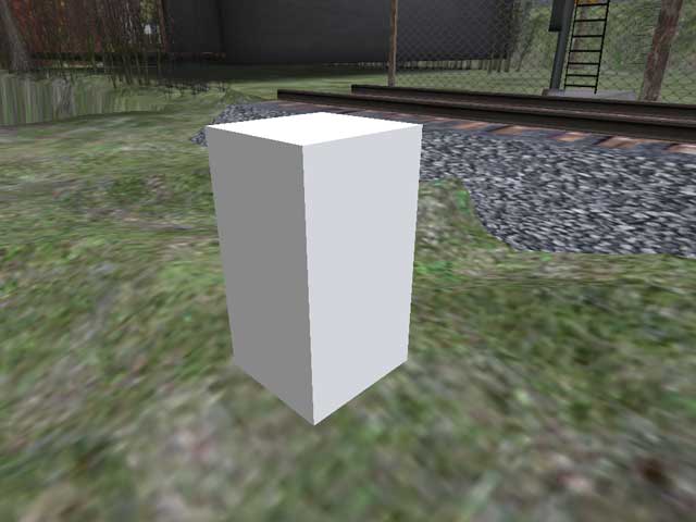
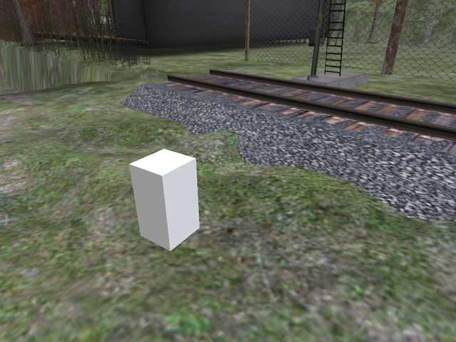
・Two Switch Stands. This is the large linkset which includes the signal stand, the dwarf light and some large alpha cubes. (Due to these large alpha cubes the object will rez over your head - look up after rezzing)
There is a left and right Switch stand. Left means the Main line heads off to the left.
Right means the Main line heads off to the right. Main and Branch orientation is up to you on private land. Though there are strict standards when attaching to the SLRR Mainlines. The SLRR Mainline is Always Main.
・Two sensors. One for the Branch, and one for the Main, tracks.
・Points. These are optional, and imitate the rail movement of a RL Switch.
・One Pin Setting Script.
OK, ready? lets go!
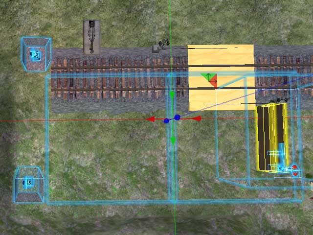
1. Positioning and adjusting the linkset:
Drag the appropriate (left or right) Switch Stand into the world. Position neatly over your junction. Take your time and use "edit linked parts" to shuffle around parts of the linkset. Dwarf signal lights will need the most fiddling. Try not to left click the linkset during this process. ( Switches come inworld in the Main Position, Setup should be done in the Main position. If you click into the Branch position, just click again into the Main position to continue setup)
Once satisfied with these modifications and all looks good, we can move on to scripts.
Once satisfied with these modifications and all looks good, we can move on to scripts.
2. Setting signal Rotations:
We need to set the Main position of all the rotating parts. This is semi-automated. ??
a) First make sure the Switch Stand is in the "Main" position. (Look at the Description of the Switch Stand. it says Main or Branch, to confirm)
b) Using "Edit Linked Parts" look closely at these signal parts' Descriptions. You will see a string of numbers there. This is the rotation they return to when "Main" is called. (these are the only parts on the swithc that are animated. to find them click the switch, click again and check that you are in the Main position)
c) Delete the numbers in each rotating signal prim's Description and replace with a single space. (space bar once).
d) Then reset the script in the prims you just edited. (Tools > Reset Scripts in Selection). The scripts will check their current rotation and write it into each prim's Description.
NOTE: This can be adjusted at any time. Simply put the Switch Stand in the Main position and repeat the above steps. (2a - 2d)
e) Once complete, cycle the Switch Stand to assure all signals rotate correctly. (click it)
(The optional Points use the exact same code. Apply steps 2a - 2d to the Points if including them.)
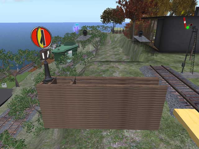
3. Setting up the Guides:
OK here is where it gets tricky and one Must stay organized. We need to assign the PIN to each Guide and record its UUID. I suggest doing one side at a time. ie: do all the Mainline Guides first, then move over to the Branch side.
(Main and branch orientation relate to the track you are building. This is up to You. Use the left or right Switch Stand appropriately)
(Also the order you choose is up to you. just try to keep organized.)
a) Drop the "Pin Setter" script into the first Guide on the Main side. It will return some chat, including a UUID.
Now do the same for the next Main Guide, and the next, until all the Main Guides have their Pins set and you have a list of UUID in local chat window....
(The order you choose is up to you. just try to keep organized.)
b) Now open the "Brainz Main 1" script, in the Switch Stand, and replace the UUID with your first Main Guide's UUID. Also, now is a good time to change the messaging channel if you need to.
(if you have more than one switch within shout distance, 100 meters, change the channel on one or the other to avoid confusion. Change the number right below the UUID where it says //change channel here.)
c) Click Compile. ( if you cant find this button, log out.)
d) To double check this worked, see if the Guide in question is changing colors from red to green as the Switch Stand is cycled. If not, check for copy/paste errors. (jsut Click the Switch Stand to Cycle it)
e) Look in the inventory of the Switch Stand again. You will see 2 "helper Main" scripts and 3 "helper Branch" scripts.
f) Open the "Helper Main 2" script and replace its UUID with your next Main Guides UUID. Then the Helper Main 3. and the Third(if needed).
g) Double check your work by cycling(click it) the Switch Stand. You should have one side of the Switch Guide flashing from red to green on command now.
h) Repeat the above steps (3a - 3g) with the Branch side. Drop in PIN Script, and add UUIDs to the "helper Branch"scripts. Check as you go, making sure things are working as expected.
i) Once this step is complete you should have Green Guides on one side and Red on the other. The colors will alternate when the Switch Stand is touched or messaged.
Yay!
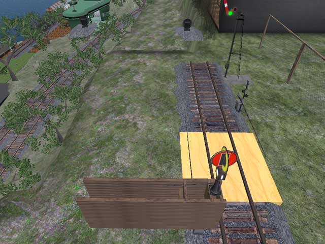
sensor automation
These sensors trigger the Switch Stand. Automating the Switch position for trains merging into the junction.
(optional)
(optional)
4. Drag a Main sensor from your inventory to the Main side of the track. place the Top of this sensor flush with the top of the Guide.
a) drag Branch Sensor from Inventory and place on Branch side of the track the same way.
5. The Final Step, and one that is important for future awesomeness:
a) Open the "Desc. changes" Script. We are writing a string into the Description of the Switch Stand. Its format is as follows: Identifier~Status~Merge~Main~Branch~Messaging Channel
b) Please fill in to the best of your ability. This will be used to create navigational HUDs and systems in the future. More information on this Strings standards can be found in the wiki.
b) Please fill in to the best of your ability. This will be used to create navigational HUDs and systems in the future. More information on this Strings standards can be found in the wiki.
extended description string info
Identifier = "Tuliptree.123.234.34"; // Put here the name of the sim where the switch stand is. And put here the location x.y.z where the switch stand is. (note the point . between x.y.z)
Status = "Main" or "Branch" // Depending on what section of the script your putting this string into.
Merge = "Calleta Hobo station"; // Put a short description of where the merge side of the switch leads off to
Main = "Tuliptree station"; // Put a short description of where the Main side of the switch leads off to
Branch = "a private railyard"; // Put a short description of where the Branch (curved) side of the switch leads off to
Channel = "134"; // Put the same channel number as you put in the "Brainz Main 1" script. This is the communication channel for all the parts of the switch.
Congratulations. Your Switch Stand is complete! Grab a train and test it. =D
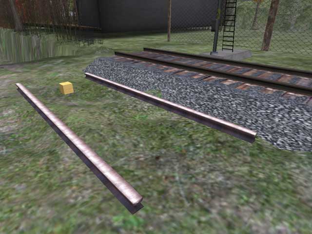
You may find some sensor trains "jump" across your switch. This is due to their sensing the wrong track and is related to how far apart the Guides are. I call it Minimum Guide distance. A 5 meter Minimum Guide Distance is best. To achieve this in some junctions, more than 6 Guides need to be changed. Perhaps 7 or 8 Guides will need to change.
Simply copy the "helper" scripts and apply Guide UUIDs to them to "Add to" the existing system.
Status = "Main" or "Branch" // Depending on what section of the script your putting this string into.
Merge = "Calleta Hobo station"; // Put a short description of where the merge side of the switch leads off to
Main = "Tuliptree station"; // Put a short description of where the Main side of the switch leads off to
Branch = "a private railyard"; // Put a short description of where the Branch (curved) side of the switch leads off to
Channel = "134"; // Put the same channel number as you put in the "Brainz Main 1" script. This is the communication channel for all the parts of the switch.
Congratulations. Your Switch Stand is complete! Grab a train and test it. =D
You may find some sensor trains "jump" across your switch. This is due to their sensing the wrong track and is related to how far apart the Guides are. I call it Minimum Guide distance. A 5 meter Minimum Guide Distance is best. To achieve this in some junctions, more than 6 Guides need to be changed. Perhaps 7 or 8 Guides will need to change.
Simply copy the "helper" scripts and apply Guide UUIDs to them to "Add to" the existing system.